Tim McLean – Managing Director of TXM Lean Solutions will talk about the different Factory Layout Examples.
When developing a Lean factory layout, many people assume that the layout must be a “U”. However, the right solution for you will depend on your process and individual needs. Here are the main Lean factory layout types:

The Types of Lean Factory Layouts
S Shaped Factory Layout
With this Factory layout example, the flow folds back on itself in an “S” shape. This layout is useful when there are many operations involved in the process and it is not possible to move these operations in to sub assembly cells.
It uses space efficiently but has the disadvantage that the ends of the “S” can be closed leading to long material handling travel times. Another problem is that the flow tends to start and finish in opposite corners of the factory.
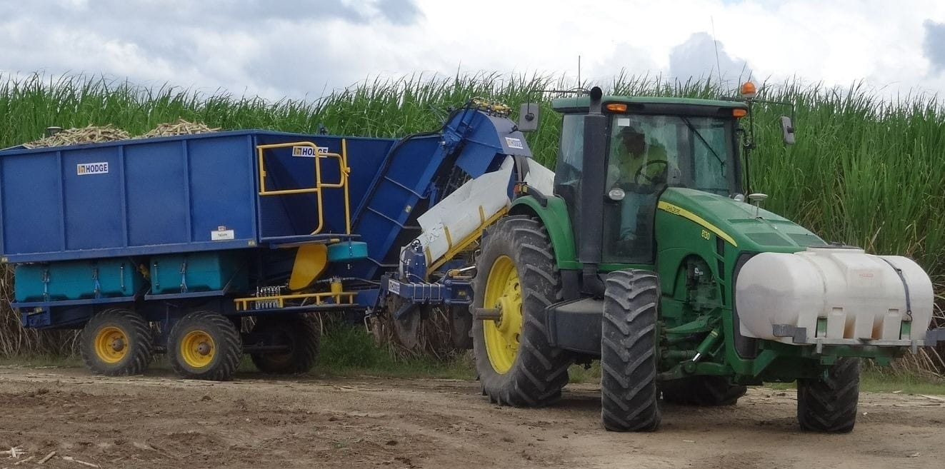
A great lean factory layout example using an “S” layout is the layout that TXM developed for Rowing boat builder, Sykes racing. This product was physically long (up to 18 metres) and involved many production steps.
A big benefit of the “S” was that enabled good use of the “corners” of the “S”. The first corner allowed for composite curing and small FIFO buffer between the lay-up and assembly processes.
The second corner enabled the composite moulds to be returned back to where they started in the mould store, minimising the transport of empty moulds (and potential damage).
U Shaped Factory Layout
In this factory layout example the raw materials enter one side of the “U” and the product travels around the “U” (usually in an anticlockwise direction) until the finished product or sub-assembly reaches the other end of the “U” where it is picked up.
Benefits of this Lean Factory Layout Example:
- Input and output of parts is relatively close together so material handler can drop off raw materials and pick up finished goods in the same trip;
- External movements of in-process part containers easier as full parts can be loaded from the outside of the “U” and picked up from the inside;
- Eliminates the required space for WIP;
- Make the supervision and visual control of operations easier;
- Increases the ability of operators to work on more than one machine or workstation. This is particularly useful if you need to ramp output up or down.
- Makes the implementation of teamwork easier as team members are working close together.

The benefits of the U Shape layout/cell are greatly reduced when large equipment or many processes are involved.
L Shaped Factory Layout
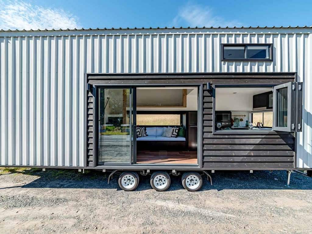
An L shaped layout example is used when the layout flows around a corner. It is usually the least space efficient as it is hard to make use of the space on the inside of the L. Also, material handling pathways to the outside of the “L” are often long. Product also starts and finishes in opposite corners of the layout.
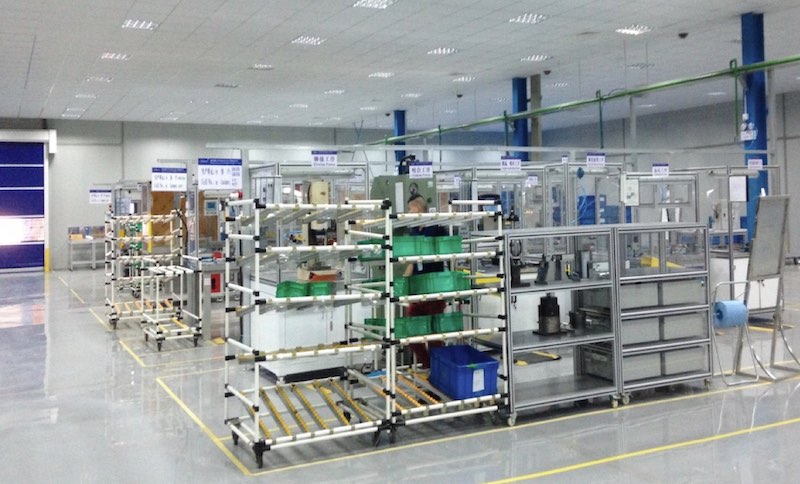
However sometimes, as in the example pictured, an L shaped layout is the only option available and an “L” shape can sometimes be “wrapped” around the outside of a “U” shaped cell to extend the flow.
I Shaped Factory Layout
The final Lean factory layout example that we will introduce is also the most common, the “I” shaped layout. “I” shaped layouts are best for processes with a small number of process steps. Essentially the flow goes in a straight line with raw material fed in one end of the “I” and finished goods out the other.
Often “I” shaped layouts will be used for final assembly and will be fed by sub-assembly cells. This often produces very short lead times and small footprints. Often several “I” shaped layouts will arranged in parallel for different products or else feeding in to a central flow in a “fish-bone”layout.
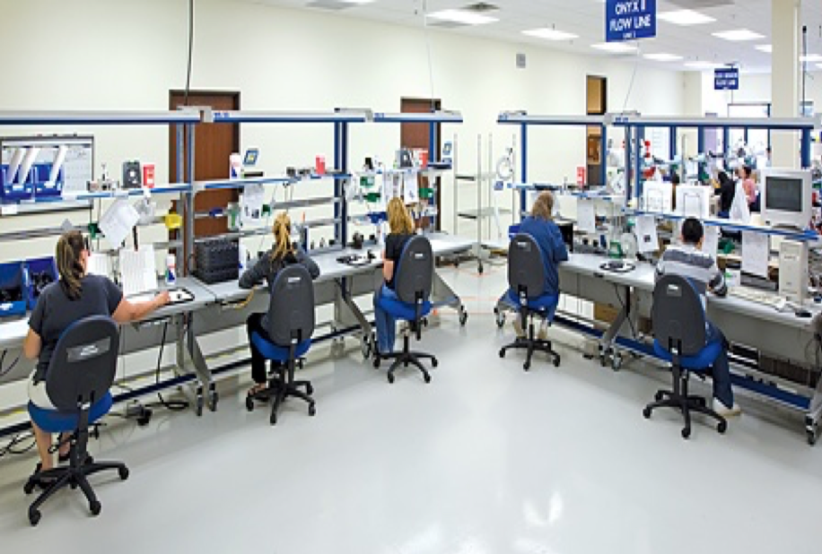
A great example of an “I” shaped layout was the layout we developed for Varian Inc for manufacture of emission spectroscopy equipment. This layout featured several “U” shaped and “I” shaped sub-assembly cells feeding directly in to a short “I” shaped layout for final assembly.
TXM Can Help with Your Factory Layout
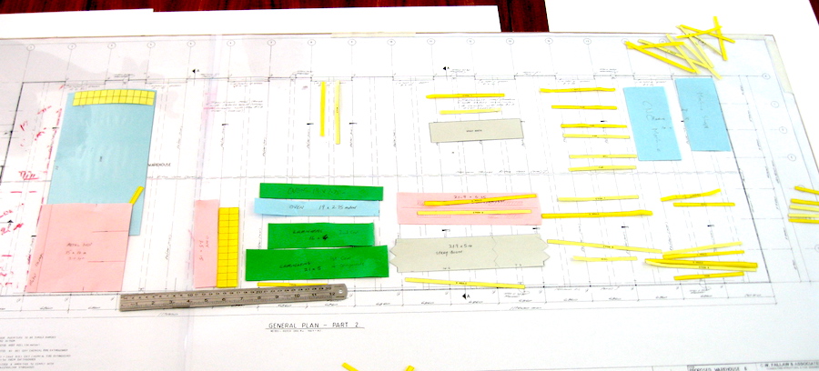
The TXM Lean Plant Layout Development Process provides the focus you need to get your team working together throughout this challenging time. It is based on understanding your business and produce flows using the Value Stream Mapping approach. From here, detailed cell designs can be determined, considering the seven flows, as outlined above, as well as the cell workload to optimise the layout for that product range.
These cell layouts are then looked at in the context of the factory to determine the best layout with the equipment and facilities you have. Then the TXM team will do it again and again until we have covered several options. This gives your team the opportunity to try out different options and layouts, noting the benefits and problems with each layout and finally coming to an agreed layout the meets most of the criteria while understanding when compromises may have been made.
The best time to improve your factory layout is before you have shifted into a new building – putting in the effort to develop a good factory layout before you have moved will save you money, time, and the stress of getting it wrong!

Author: Timothy McLean
Timothy McLean is the Managing Director of TXM Lean Solutions and is an author of Lean books.